Review material information, section properties, attachment options, specification sheets, and layout factors for SnoBar and ColorBar snow rail systems used on compatible metal roofs.
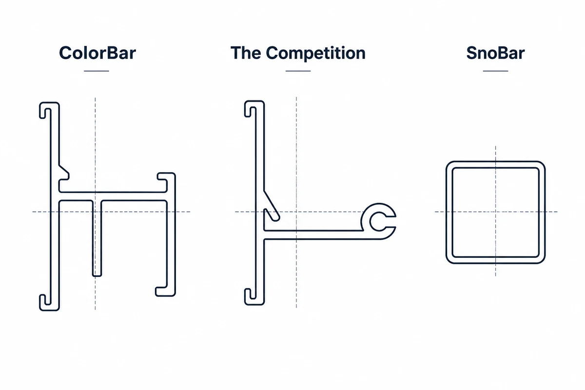
Profile comparison showing ColorBar, a competing aluminum snow rail profile, and SnoBar. The cross-section shapes help explain differences in area, moment of inertia, and section modulus values.
Material DataSection PropertiesClamp OptionsBracket OptionsSpecification Sheets
Technical Overview
This page organizes SnoBar and ColorBar technical information into a cleaner reference format for architects, contractors, metal roofing professionals, and building owners evaluating bar-style snow retention systems.
Technical data is provided for planning and product comparison only. Snow retention layouts should also consider roof structure, panel profile, panel gauge, seam height, snow load, building use, and hazards below the roof edge.
System Profiles
SnoBar and ColorBar are both bar-style snow retention systems, but they use different materials and profile designs.
SnoBar
SnoBar Square Steel Rail
SnoBar is a square steel snow rail system available in galvanized or stainless steel for standing seam and exposed-fastener metal roof applications.
Square rail profile
Gator coated galvanized finish
Stainless steel bar options
Stainless or aluminum clamp attachments
Screw-down bracket options
Powder coating options
ColorBar
ColorBar Structural Aluminum Rail
ColorBar is a structural aluminum snow rail system designed for strength, clean finished appearance, and optional powder coating or color-strip matching.
Structural aluminum profile
6061-T6 extruded aluminum rail
Stainless or aluminum clamp-on options
Optional color-strip or powder coating
Screw-down attachment options
Aluminum splice connector for continuous runs
Section Properties
Section properties help compare how each snow rail profile resists bending. Higher section modulus values generally indicate greater resistance to bending about that axis when comparing similar loading conditions. These numbers show ColorBar’s profile geometry is stronger/more efficient than the listed competing aluminum profile for bending resistance.
Property
ColorBar
Competition
SnoBar
Profile Type
Structural aluminum profile
Competing aluminum profile
Square steel rail profile
Area
0.59
0.45
0.23
Ix
0.15
0.12
0.03
Iy
0.19
0.13
0.03
xmax
0.89
1.16
0.50
ymax
1.17
1.23
0.50
Wx = Ix / ymax
0.13
0.10
0.07
Wy = Iy / xmax
0.21
0.11
0.07
xmin
0.70
0.55
0.50
ymin
0.95
0.89
0.49
Wx2 = Ix / ymin
0.16
0.14
0.07
Wy2 = Iy / xmin
0.27
0.23
0.07
Measurement Step
0.005
0.01
0.01
ColorBar has higher section modulus values than the listed competing profile in this comparison. SnoBar is shown separately as a square steel rail profile. Final system selection should also consider roof type, attachment method, seam height, panel gauge, roof run, snow load rating, and project location.
Center of an Area
The center of an area, or centroid, of a shape is the point at which it is in equilibrium. If a shape is supported at this point, it is in a state of equilibrium and should not fall off.
A useful analogy is the center of gravity or center of mass. The center of different shapes cut from cardboard can be found by hanging each shape from a string. The line of action will always pass through the center of gravity of the particular shape.
The center of gravity is not necessarily within the body of the shape. It can fall outside the shape, as with many angular forms. A more precise procedure to find the center of gravity is the first moment of area method.
The position of the center of gravity of a compound body can be found by dividing the body into several parts where the center of gravity of the individual parts are known.
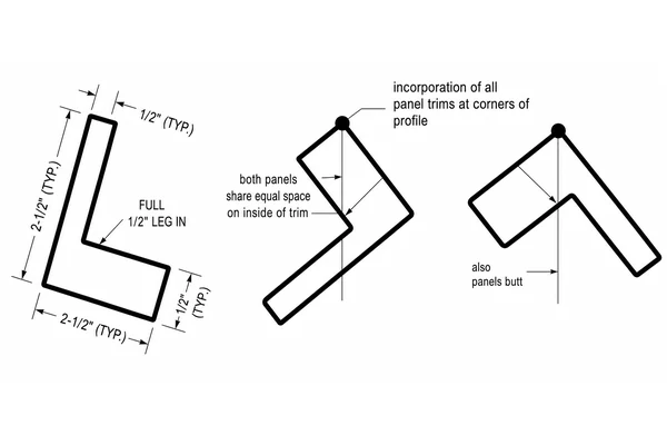
Diagram showing profile shapes and reference lines used to explain how area distribution affects the center of an area.
First Moment of Area Method
The following method applies:
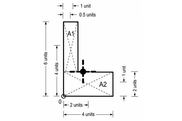
Divide the body into several parts, such as A1 and A2.
Determine the area or volume of each part.
Establish a reference point for taking moments.
Determine the distance from the reference point to the center of gravity of each individual part.
Take moments about the x-axis and y-axis to determine the center of gravity of the whole body.
Compound body diagram divided into A1 and A2 areas for centroid calculation.
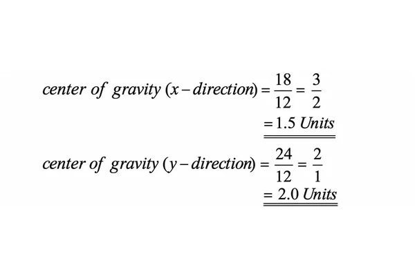
Center of gravity results showing the calculated x-direction and y-direction values for the compound body example.
Dimensions
Area
Distance to Center of Mass
Area Moment
Length 4, Width 1, A1
4
x = 0.5, y = 1.0
x-axis = 4, y-axis = 2
Length 4, Width 2, A2
8
x = 2.0, y = 1.0
x-axis = 8, y-axis = 16
Total
12
-
x-axis = 24, y-axis = 18
The center of gravity is found by dividing the specific area moment by the total area. In this example, the center of gravity is:
x = 18 / 12 = 1.5 units and
y = 24 / 12 = 2.0 units.
Section Modulus
Section modulus is used to help express the relationship between bending moment and bending stress in structural members. For snow rail profiles, it helps compare how efficiently each profile shape resists bending under load.
What Section Modulus Means
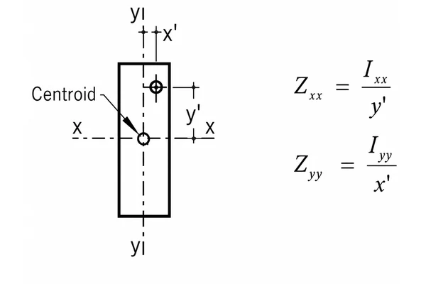
To calculate bending stress in structural members, such as beams or snow rail profiles, a property called section modulus is used to express the bending moment and stress relationship.
Each point within a cross-section can have a section modulus. This is the ratio of the second moment of area, also called moment of inertia, to the distance between a point within the section and the relevant neutral axis.
The maximum stress occurs in the extreme outer fibers of the section, so the distance from the neutral axis to the outermost point is important when evaluating bending stress.
In simple terms: a rail profile with more material placed farther from the neutral axis can often provide greater bending resistance than a profile with the same or less material concentrated closer to the center.
Section modulus diagram showing centroid axes, moment of inertia, and the distance from the neutral axis to the outer fibers.
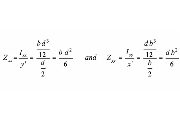
Section modulus formulas showing how Zxx and Zyy are calculated for a rectangular section.
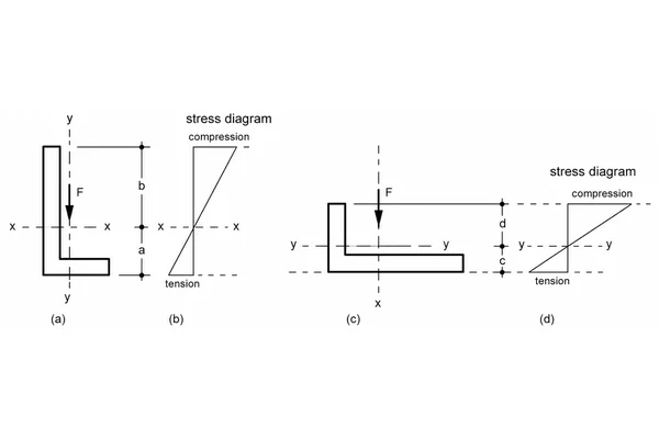
Asymmetric section modulus diagram showing how different distances from the neutral axis to the outer fibers create different tension and compression values.
Term
Meaning
Why It Matters
Moment of Inertia
A measure of how the cross-sectional area is distributed around an axis.
Higher values generally indicate greater resistance to bending and deflection.
Section Modulus
The moment of inertia divided by the distance from the neutral axis to the outer fiber.
Used to compare bending stress capacity of different rail profiles.
Neutral Axis
The axis in a cross-section where bending stress changes from compression to tension.
Asymmetric profiles may have different distances to the extreme fibers on each side.
Extreme Outer Fiber
The farthest point of the section from the neutral axis.
Maximum bending stress occurs at the outer fibers.
Symmetric vs. Asymmetric Profiles
For a symmetric rectangular or square profile, the distance from the neutral axis to the outer fiber is typically the same in each direction. For example, a square steel rail has a more uniform section shape.
For an asymmetric profile, the distance from the neutral axis to the outer fiber may not be the same in every direction. Because of this, more than one section modulus value may exist for the same axis.
This is why ColorBar and competing aluminum profiles may show values such as Wx, Wy, Wx2, and Wy2. These values represent section modulus calculations based on different distances from the neutral axis to the outer fibers.
Section modulus is one of several technical factors used to compare rail profiles. Final snow rail selection should also consider attachment method, roof panel type, seam height, panel gauge, roof run, snow load rating, project location, and hazards below the roof edge.
Additional Engineering Reference Concepts
These technical concepts help explain why rail profile shape, material, depth, and attachment method matter when comparing snow rail systems.
Area Distribution
The amount and location of material within a rail profile affects how the rail responds to bending loads.
Profile Shape
Square steel rail profiles and structural aluminum rail profiles distribute material differently, which affects section properties.
Attachment Method
Standing seam clamps and screw-down brackets transfer snow loads differently, so attachment method must be reviewed with the roof panel type.
Attachment Methods
SnoBar and ColorBar snow rail systems are selected based on the roof panel type, structural requirements, and whether the roof uses standing seam or exposed-fastener panels.
Standing Seam
Stainless Steel Clamp Mounts
Stainless steel clamp-on attachments are used for compatible standing seam roof panels where non-penetrating attachment is required.
SnoBar should be described as a square steel rail profile. ColorBar should be described as a structural aluminum rail profile.
Final Layout Review
Row spacing, attachment spacing, and kit quantities should be reviewed after roof pitch, roof run, panel rib spacing or seam spacing, seam height, panel gauge, project location, and snow load information are known.
Need Help Applying This Technical Data?
Send your roof information, panel details, seam height, panel gauge, snow load rating, and photos so the correct SnoBar or ColorBar system can be reviewed.